- Fundamental Logic of Wind Resistance Design: From “Force Analysis” to “Load Transfer”
The essence of wind resistance in sliding doors lies in their ability to withstand wind pressure loads and control deformation. Australia’s building codes clearly define wind pressure levels across different regions — in coastal areas, the basic wind pressure ranges from 0.5 to 1.0kPa, while in cyclone-prone zones like northern Queensland, it can exceed 1.5kPa. Design must align with these regional wind pressure ratings, establishing a complete logic of “load bearing — force flow transfer — deformation control.”
Materials used must be robust enough to ensure real wind resistance. Given Australia’s diverse and complex climate, sliding doors require sufficient wind resistance to adapt to varying weather conditions.
Types of Wind Pressure and Their Design Responses
Wind pressure on sliding doors is categorized into:
Positive Pressure: Wind directly pushes against the door panel, risking deformation, hardware loosening, or complete dislodgement.
Negative Pressure: Wind pulls from the outside (e.g., a cyclone creating low pressure on the side of the building), causing potential seal failure or glass breakage.
Shear Force: Angled wind induces lateral thrust, which can crack the connection between the door frame and the wall.
A comprehensive wind-resistant design must simultaneously address all three forces:
Positive pressure requires rigid door panels and robust hardware.
Negative pressure demands reinforced sealing systems and secure glass fixing methods.
Shear force necessitates structurally anchored door frames.
Core Technologies: From Material to Structural Reinforcement for Wind Resistance
Profile Selection: Material Rigidity as the Foundation
Profiles form the “skeleton” of sliding doors and must balance strength with lightweight properties to prevent overloading hardware.
Aluminum Alloy Profiles: The mainstream choice in Australia, recommended with a wall thickness of at least 1.4mm for standard use, and ≥1.8mm for high wind pressure coastal zones. Multi-chamber designs (minimum of 3 independent cavities) enhance torsional resistance. These cavities can be filled with polyurethane foam to boost rigidity while improving insulation, in line with Australia’s NCC energy requirements.
Steel Reinforcement: In high wind pressure regions (e.g., Cairns, Darwin), galvanized steel reinforcements (≥1.2mm thick) can be embedded within the aluminum profiles. This “aluminum-clad steel” structure enhances bending strength by over 40%. The steel must be mechanically interlocked with aluminum to prevent loosening due to thermal expansion.
Limitations of Wood: Solid or composite wood profiles are prone to deformation from moisture and are only suitable for inland low wind pressure zones (e.g., inland South Australia). They must be treated with fluorocarbon coatings for UV resistance and feature expansion joints (1-2mm wide) at frame joints to prevent jamming from deformation.
Profile connections should use corner connectors combined with mechanical screws rather than pure welding, as welding can develop microcracks from thermal stress, worsening under repeated wind loads. Mechanical connections with elastic pads (e.g., EPDM rubber) help buffer stress.
- Door Panel Structure: Balancing Rigidity and Weight Reduction
The door panel directly bears wind pressure, and its deformation must remain within regulatory limits (maximum deflection ≤ 1/200 of the span).
Glass Configuration: Glass makes up over 70% of the door panel area, critical for wind resistance. Double-layer laminated tempered glass (≥5mm+5mm) is required, with an interlayer (PVB film ≥0.76mm) preventing shattering. In high wind areas, upgrading to a composite of tempered glass and polycarbonate sheets is advised — polycarbonate offers 20 times the impact strength of regular glass.
Glass should be secured with a combination of silicone structural adhesive and mechanical clips. The adhesive fills the gap between glass and profile (5-8mm wide), while aluminum alloy clips should be installed every 300mm along the glass edges to prevent detachment under negative pressure.
Reinforcing Bars: Frames and mullions (vertical dividers) of the door panel must include reinforcements. Mullions should be one-piece, not segmented, and connected to the frame using mortise-and-tenon joints plus stainless steel screws (spaced ≤300mm) to create a “mesh support structure” that disperses wind pressure.
Weight Optimization: While ensuring rigidity, optimize profile cross-sections (e.g., using streamlined edges to reduce wind resistance) and use lighter glass options like ultra-clear glass with reduced thickness to control overall door weight, avoiding hardware fatigue from prolonged loads.
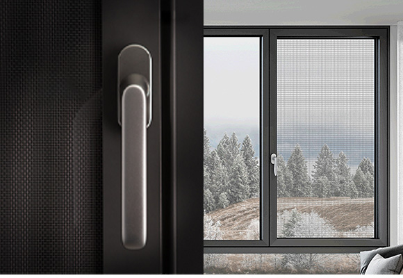
- Hardware System: The “Joints” Safeguarding Wind Resistance
Hardware is the “movable joint” of sliding doors, and its load-bearing capacity and stability directly affect wind resistance limits.
Tracks and Rollers: Dual-track systems are necessary (upper track for load-bearing, lower track for guiding). The upper track should carry over 70% of the door panel weight to prevent sagging from wind-induced deformation. Track profiles must be ≥2mm thick with built-in stainless steel rails (chrome-plated for rust resistance). Rollers should feature a dual-wheel system (each wheel diameter ≥20mm) with sealed ball bearings (dust and salt-resistant). Each roller assembly must support ≥100kg; for double-panel doors, at least 4 roller assemblies are required.
Locking System: Crucial for wind resistance, adopting a multi-point lock system with at least 3 locking points (top, bottom, middle). Lock engagements should have a depth of ≥5mm, made from 304 stainless steel for corrosion resistance. Lock rods must be solid steel (≥8mm diameter), bolted (not riveted) to the door profile to prevent pull-out under negative pressure. For extreme wind areas, an “electromagnetic lock” upgrade is advisable, where electromagnetic force enhances sealing tightness when closed.